BASIC MESH CREATION AND EDITING
Before I start, you will need to be familiar with some of the terminology. You
will more than likely be familiar with these terms if you have made models for
Quake2 or used any other modelling package, but I'll explain them anyway.
Model meshes are made up of three things: Vertexes, Edges and Faces.
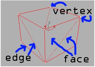
Edges are the lines that make up the wireframe. Where two or more edges converge
or intersect is a vertex. Vertexes connect the edges. Faces are the surface area
created when you have three edges creating a triangle. On most stock models, the
wireframe will appear to have square faces. This is an illusion. This is two
triangles making up a rectangular face. When you export a model to TF2 ,
this will appear as two triangles and will be considered by the game to be two
faces, not one!
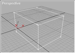
I'll begin with some simple mesh-editing. Create a cube. Do this by clicking the
'create' tab in the top right...

and select 'box'. Select a viewport and holding down the left mouse button drag
a square in the viewport. You will draw a rectangle. once you release the button
the rectangle's size will be set. Drag the mouse again to set the box's depth.
You should see the box expand in one of the other viewports. Once you click the
button again the box will be created.
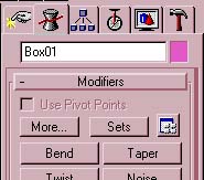
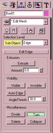
Now go to the modifier rollout...

If you set up your modifier buttons as I suggested in the first section, then
simply click the 'Edit Mesh' button. If you didn't then you will need to do the
following: Select 'More'.
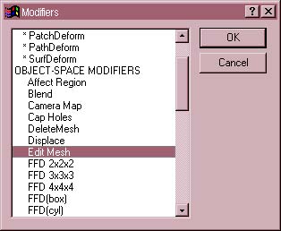
From the list you are given, scroll down until you find 'Edit Mesh' Double click
this item to apply the modifier to the mesh.
You will notice that the object has aquired cross-vertexes on all the
edge-junctions or corners. You are now able to edit the faces, vertexes and
edges.
You will notice that under the modifier rollout there is a 'Sub-Object' button.

When this is activated it turns yellow, This means that you are at sub-object
level and you are editing individual vertexes, faces and edges. Notice that in
the box next to it is the word 'Vertex'. This means that you are in vertex
editing mode. If the 'Sub-Object' button is deactivated, then any modifications
that are made affect the mesh as a whole. If you wish to stop editing the mesh
of one object and move to another, you won't be able to do so until you have
de-activated the 'Sub-Object' button.
Something to remember when editing a mesh, try to avoid editing in the
perspective viewport. Due to it being an off-set view, adjusting edges, vertexes
or faces can have unpredictable results. Use the side, top and front views only.
It does make sense, however to select objects in the perspective viewport.
However, make sure that you right click and not left-click when you select a
viewport to work in otherwise your selection will be deselected.
I will begin with vertexes.
VERTEXES
Make sure you have the sub-object activated and the vertex
mode selected:

Select a vertex. This can be done by clicking on any vertex or by drawing a box
around it by holding down the left mouse button and dragging across the vertex
until it is boxed in. You would use this latter method to select multiple
vertexes.
You will notice that any vertexes you select will now turn red.
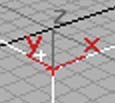
For now, select only one vertex, remember that if you are selecting a vertex
using the drag-box method in a view where an edge joined to that vertex points
away from you, it will also be selected but it will be behind the vertex you
intended to select so it will seem as if you have only selected one.
Now you can adjust that vertex. try moving it. Select the move tool from the top
bar.

Move the pointer over the vertex you have selected and it should alter to the
move tool symbol. Once this happens you are able to move the vertex. Taking care
not to move the pointer, hold down the left mouse button. Now move the mouse and
the selected vertex is moved also.
What if you wanted the vertex to move sideways but not up or down? It is
possible to lock the movement of the move tool.
You will notice a series of letters on the top bar.

These are movement locks for the tools. You will notice that XY is highlighted
as a default. If you click on X and then try moving the vertex, you will notice
that it will only move sideways (along the X plane) and not vertically. If you
click the 'Y' button, the vertex will only move vertically. By clicking 'XY'
again, the vertex will move all directions.
Notice at this point that whichever viewport you have selected, X points
horizontally, Y points vertically and Z points toward you always. You will
notice that this is not the case with the other viewports, until you select one
and the XYZ 'gizmo' changes.
Okay, now try again, this time select a group of vertexes by boxing them in. Try
the direction locks again.
Okay, let's say you wanted to resize a group of vertexes. First select two or
more vertexes and then select the resize tool.

Move the resize tool over one of the selected vertexes until the pointer changes
to the resize tool symbol. Now hold down the left mouse button and drag down.
You will see that the computer has determined a common center to the group of
vertexes and shrinks them all toward that point. Now push the mouse forward. You
will see that the vertex group expands away from that point.
Let's say you wanted to shrink a group of vertexes vertically but not
horizontally.
put the mouse pointer over the resize tool and hold down the left mouse button.
You will see three tools drop down.
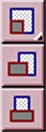
The top one is the standard uniform resize tool. The middle is the non-uniform
resize tool. Select this by keeping the left mouse button pressed and drag down
to it.
You are now ready to resize the selected vertexes non-uniformly.
Again, you use the XYZ direction locks to determine which direction the mesh is
shrunk in.
Like the move tool, it is possible to shrink in the X and Y directions, but with
the non-uniform resize tool, you can shrink in two different directions at once.
You will notice that XY is once again the default. If you click and hold on XY,
you will notice a new list drop down: XY YZ ZX.

By selecting one of these, the non-uniform resize tool will shrink the object in
the selected two directions but not the third.
Try altering a group of vertexes.
Okay, rotating vertexes is similar again. You select your group of vertexes and
select the rotate tool.

Once you place the pointer over one of the vertexes, it will change to the
rotate symbol and, holding down the left mouse button, drag down or push forward
and the vertexes will rotate around a common center.
Okay, next is 'welding' vertexes.
Select two vertexes. Go to the rollout parameters and you will see the 'Weld
selected' button
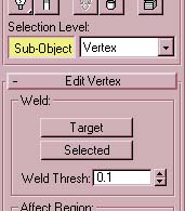
the 'Weld Thresh' is the maximum distance that vertexes can be apart before the
computer will weld them. The vertexes you have selected must be closer than this
or the computer will not weld them and display the message: 'No vertices within
weld threshold'
Select two vertexes. They need to be VERY close together. I generally move them
together using the 'MOVE' tool and then once they are as close as I can get them,
I use the uniform resize tool and shrink them together. Once they appear to be
joined, I weld them.
To weld two or more vertexes together, simply click 'Weld Selected'. If you get
the following message,
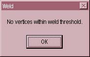
It means that the vertexes are too far apart, either move them closer or raise
the weld threshold until they weld.
By welding two or more vertexes, you will delete the faces in between them.
FACES
You will notice that next to the 'SUB-OBJECT' button is a drop-down menu with
the word 'Vertex' displayed. Drop this menu down and select 'Face'

You are now in face-editing mode. If you click or drag on the mesh that you are
editing, you will notice that instead of vertexes being selected, faces on the
mesh are being highlighted red.
In the same way that you moved, rotated and resized vertexes, faces can also be
altered. try it.
Where Faces differ from vertexes is this:
They can be 'extruded'. Select a face and go to the extrusion box on the
modifier roll-out.
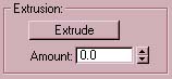
Click the 'Extrude button' and use the arrows next to the Amount box by clicking
on one and holding down the mouse button. Now push forward or pull back and the
numbers in the amount box will increase or decrease. As the Amount increases or
decreases notice that the face you selected moves away from or toward the object
creating new faces at right angles to itself, adjoining it to the rest of the
mesh.
You can create more accurate extrusions by typing the exact amount you wish to
extrude in the 'Amount' box. Alternatively, once you have selected a face, click
the 'Extrude' button and drag the face in one of the viewports.
EDGES
Once again drop down the Sub-Object menu and select 'Edge'. Now when you drag
and select in the viewport, you will notice lines in the wireframe being
highlighted red. Once again, as with Vertexes and Faces, Edges can be resized,
moved and rotated in the usual way. There are, however two useful things that
you can do with edges.
The first is that you can 'Turn' them. This enables you to get better curvature
on faces.
Go to the modifier parameters rollout. Slide down until you find the Turn button.
Click it and it should highlight green. Now click on any edge that you wish on
the mesh that you are editing. Notice how it rotates to link between two other
vertexes other than the two it was originally joined to.
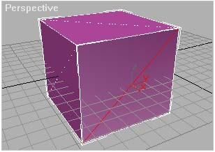
This is the selected edge before turning is applied.
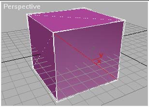
This is after turning is applied.
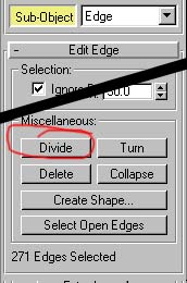
The second useful thing that you can do with edges is divide them. Again, slide
up the modifier rollout and click on the 'divide' button.
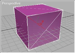
Now click on any edge in the mesh that you are editing. You should see a vertex
appear in the center of the edge and two new edges appear, projecting from the
new vertex.
This is the edge before dividing.
This is the edge after dividing. The edge is now divided at the center. The Face
now has four triangles or faces instead of two.
This is particularly handy for creating new, smaller faces in a larger more
general mesh.
This is the basics and all you need to know to create a mesh-model.
Tutorial created by Scarecrow,
THANK YOU !!!
©
http://www.Planetfortress.com/TF2Models
TF2 is trademark of Valve
Software and of Sierra Online.
© 2000 TF2 MODELS - Hosted by Planetfortress
Web designer/Webmaster : IXNAY