FIGURE MODE


So, we have our biped built and configured as we like it. You may have created your own Biped, or you may have simply used the Gordon Biped. For the purposes of this tutorial I shall assume that you are using the Gordon Biped (that I provided on the previous page).
If you are making a purely humanoid model, the same size and dimensions as Gordon, then you are ready to go. However, should you wish to deform or add bones to the Biped, then you will need to activate 'Figure mode'.

For our purposes, there are two states to a Biped, 'Figure mode' and 'Non-figure mode'. Non-figure mode is the default setting. It is the mode you use for animating the biped. In this mode you can rotate and move the limbs of the biped, but you cannot alter their shape.
NOTE: Any changes made to the Biped in non-figure mode will only be retained if the 'Animate' button is activated.
In 'Figure mode', It is possible to alter the shape, size and position of the Biped. any changes made to the Biped are permanent, wether the 'Animate' button is active or not, and carry across in to 'Non-Figure mode'.

To activate Figure mode, go to the 'Motion' tab, with the unicycle on it. As long as you have a part of the Biped selected, you will see a rollout of Biped controls. You need to click the 'Figure Mode' button about half way down the Motion/Biped rollout.


Click this button and you will be in 'Figure mode' and we can proceed.

CUSTOMISING THE BIPED


Firstly and most importantly, it is possible to alter the structure of the biped.
Go down to the bottom of the rollout to the bar which says, 'structure' and click it.


A rollout will appear and you can now edit the structure of your Biped.


Following is a brief description of the parameters and their uses.

ARMS: The arms check box literally dictates wether there are arms on the model or not.
NECK LINKS: This has a value from 1 to 5 and sets how many segments there are in the neck. The Valve Biped has 1.
SPINE LINKS: This has a value of 1 to 5 and sets how many segments there are in the spine. The Valve Biped has 3.
LEG LINKS: This has a value of 3 or 4 and sets the legs as either human or dog. The Valve Biped has 3 (human).
TAIL LINKS: This has a value of 0-5 and sets how many links there are in the tail. It extrudes from the pelvis bone, 'Bip01 Pelvis' and a setting of 0 means no tail. The valve Biped value is 0.
PONYTAIL 1 and 2 LINKS:These work the same as the TAIL LINKS, but protrude from the back of the head instead. A setting of zero means no ponytail. The Vlave Biped has a setting of zero. Gordon's ponytail was boned using MAX standard bones.
FINGERS:This has a value of 0 to 5 and sets the amount of fingers that a biped has. Once the setting reaches 4 then one of the fingers will become a thumb, however it is possible to reposition one of the fingers as a thumb, should you wish to have less than four (more later). The Valve Biped has a setting of two. One finger and one thumb.
FINGER LINKS: This has a setting from 1 to 3 and dictates the ammount of segments in each finger and thumb. Valve has a setting of 3
TOES: This has a setting from 1-5 and dictates the ammount of toes the Biped has on each foot. Valve has a setting of 1.
TOE LINKS: Has a setting from 1 to 3 and like fingers, dictates the ammount of segments in each toe. Valve has a setting of 3.
ANKLE ATTACH: This offsets the foot on the ankle. The value is 0.0 to 1.0
HEIGHT: this adjusts the size of the biped, centred at Bip01.

Once you are satisfied with the structure of your biped, we are ready to adjust the general size and shape of each part...

ADJUSTING THE SHAPE

...or cosmetic surgery for bipeds.


Allright. We have set the amount of spine links, fingers and tail links that our new Biped needs (should you wish to alter them from the original Gordon Biped at all). Now what if you want the arms to be longer or fatter or the head to be bigger or the torso to be wider? Well. That's the next step. Elements of the Biped can be deformed in exactly the same way as primative objects. Using the linear and non-linear scale tool, but only, as I keep saying, in 'Figure mode'.

TIP: It makes sense at this point to have your mesh present on the screen so that you can adjust the skeleton to fit the mesh exactly.

You will find, at this point that elements of the Biped do not correspond to the usual X,Y and Z move and rotate laws that most objects do. The elements of the biped retain their own local X,Y,Z movement parameters and adhere to them regardless of which viewport you are using. This can get annoying, but you'll get used to it.
To explain: Ordinarily, in a 2D viewport (front, sides, top etc...), X is horizontal, Y is vertical and Z is toward you. Not so with Biped. If you select each limb, you will see the X,Y,Z gizmo rotated to demonstrate which direction each pertains to. For example, the upper leg: Z rotates forward and backwards. Y rotates left to right and X rotates along the length of the limb, regardless of which viewport you are working in.
The same applies to scaling the object.
As for moving bones. Well, it is possible to disconnect fingers and toes by moving the first link in each finger or toe (nearest the hand or foot) and reposition the fingers or toes anywhere on the biped. This is handy if you want to simply have one finger and one thumb. However, it is only possible to do this with the fingers and toes and no other part of the Biped.

COPY POSTURE


Okay, so we have scaled an arm and it looks fine for the model we wish to fit it to:


Now with a bit of care and precision, it is possible to get the other arm to look identical. However, it's a lot easier with the 'Copy Posture' button. You will see over on the right hand side, a bar titled, 'Keyframing' and under it a single icon highlighted:


This is the copy posture button. If you click it, it will save the position and scale of any selected parts of the Biped to the clip-board. This means that you can then paste the same information to the same parts of another biped. Also it is possible to paste the same information, reversed to the other side of the Biped. Select the objects you wish to mirror. Here I have selected the entire arm:


Then click the 'Copy Posture' button and two buttons will highlight underneath it:


These are 'Paste Posture' on the left and 'Paste Posture Opposite' on the right.
Clicking 'Paste Posture', will load the copied position data into the same arm or into the same arm on another Biped if you select it.
Clicking 'Paste Posture Opposite', will load the data, reversed into the opposite arm on the selected Biped. Give it a go:


ADDING BONES


As we have seen already, should you wish to add a tail or a ponytail (or two) to the model, it is possible to do so, in the Biped structure settings. However, if you wish to add bones for a mouth (as with the hi-res models in HalfLife), or extra arms or a third leg, or maybe a couple of extra links to an existing tail, you need to add bones to the existing structure.
This can be done in several ways. Valve do this by using standard Studio MAX bones. I despise Studio MAX bones however and I prefer instead to create my own using primative boxes.

To use Studio MAX bones, you need to go to the 'System' tab on the right again and select 'Bones'. Then uncheck the 'Create End Effector' box otherwise this does all kinds of wierd locking things to the bones later on when you try to animate.


Okay, now click once on the screen and release, then move the mouse and you will create a line. Click again and another bone will appear. Keep going until you have enough bones. Now right-click and the current bone will be deleted back to the previous one and the Bone creation will be deactivated.


The method I generally employ is actually far more complex, but I find it somewhat simpler in the longrun, and that is to create a primative BOX, adjust it to the right size for the bone I want and position it. Repeat this until you have all the bones you need the right size and shape.
TIP:If you wish to create several boxes the same size and shape, simply hold down the SHIFT key and move the original bone. A new box will be made identical to the original. This is true of any object.


You will then need to adjust the pivot in each bone. Do this by selecting each bone and then under the 'Heirarchy' tab, select 'Affect Pivot Only'.

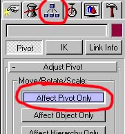
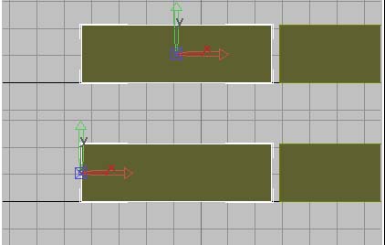
You can now freely move the pivot of the selected object with the move tool.
Incidentally, this is true of any object.
The reason we do this is because, if we don't, once the boxes are all linked together in a chain, they will still rotate around their centrepoint and not the point at which the bone connects to it's 'Parent' bone. You need to move the pivot to that point. Generally it is the nearest end of the object to the Biped (but not always).


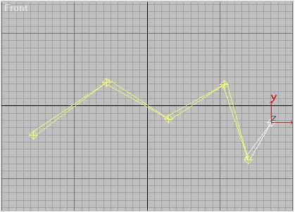
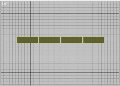
So you have created a chain of boxes to use as bones, but they are not linked together. To link them, you need to use the linking tool, which you will find in the top left of the main tool bar:


Click this button and then select the furthest bone from the biped. For example in a tail, it would be the bone at the tip of the tail. This is known as the 'child'.

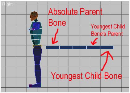
To explain: In a series of linked bones or objects, there must be a root bone. This is the bone which affects all others. it is known as the parent bone. The next bone attached to it is the parent bone's 'Child'. The Child will affect all bones linked to it, but NOT it's parent bone. This 'Child' bone will, in turn be the parent to the 'child' that comes after it, and so on and so on until the end of the chain. There MUST be a parent (root) bone and (provided there is more than just one bone in the link), a 'Child'. Bone chains CANNOT be linked in a loop. There would be no absolute parent bone in this event and MAX will tell you that it cannot create a 'Dependancy Loop'. Having said this, it is possible to 
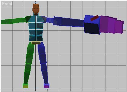
have several chains attached to the same Parent. In the Biped, Bip01, the Diamond bone in the pelvis (not the pelvis itself), is the 'Parent Bone' and several chains branch off from it, namely the arms and legs.


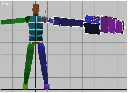
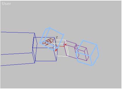
So, we select the 'youngest', 'Child' bone in the chain we have created, using the link tool. Keep the left mouse button pressed and drag across to the bone which you intend to be it's 'Parent'. Once you are over the bone, if it is a legitimate possiblity for a parent bone, the pointer will change to a 'link' symbol identical to the one on the Link button. Release the mouse button. The parent bone will highlight for a second. The child is now linked to the parent. Repeat this along the chain. In turn linking the first bone's parent to it's own parent, until you reach the Biped itself.
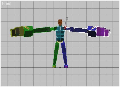
To test the link, rotate the Parent bone to see if the Children follow.

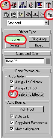
NOTE: IF you are using MAX's standard Bones, you do not need to link them, they automatically link to each other as you create them. However you will need to link the absolute Parent bone in the chain to the Biped at a relevant point. For example, if you were creating a tail, you would link the tail's absolute parent bone (the bone nearest the Biped) to the Pelvis. Alternatively, if you were just adding extra bones to the Biped's tail, you would link the absolute parent bone to the youngest child in the Biped's tail.

When creating MAX standard bones, the first bone you create will be the root and any bones you create afterward will become the child of the one previously.

Also, When you link a root bone (the absolute parent) to another bone (ie a bone in the biped), that new bone become's the rootbone's parent and the root bone is no longer a root bone or the absolute parent, the new bone is. And if that bone itself, is at the end of a chain, it will also not be the 'root' bone or absolute parent. For example, the absolute parent root bone in the tail I have illustrated above is the first bone nearest the Biped. If I link that to the Pelvis bone in the biped, the Pelvis bone is, in turn linked to Bip01, as is everything else. So, Bip01 becomes the root bone and then the Pelvis is it's 'child' and the bone which was the root bone in the tail is now simply the Pelvis's 'child' and so on...

DUMMIES


If you study the Biped close enough you will see that at the end of each chain (fingers, toes and head), there are small blue boxes. These are known as Dummies.


Dummies are 'helpers'. Helpers are small gadgets which have been included in MAX to assist with modelling and animation. Dummies are designed to be linkable objects but they do not render, thus they can be used as handles or controllers, or in the case of biped, to represent the end of a bone chain. When you apply the physique modifier to a mesh, the physique wire extends along each bone chain and stops at the last-but-one bone. Because of this, Dummies are attached to the end of each chain, so that the physique modifier sees each dummy as the last bone in each chain, and the physique wire stops in the last actual bone instead.
So what? Well if you have added bones to your Biped, then you will need to link a dummy to the youngest child bone in the new chain of bones.
To create a dummy, you need to go to the Helpers button under the 'Creation' tab.


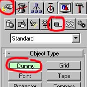
Click the 'Dummy' button and then in the viewports, at the tip of the youngest child bone in your chain, click and drag. A new Dummy cube will be created. Now link this to the youngest child in the chain of bones and you are set.

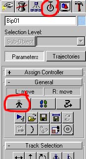
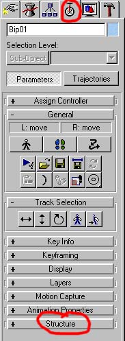
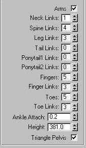
Okay, if you have set the structure of your Biped and adjusted it's shape and added any bones you need to add. Then you are ready to animate...


Next Page...


Tutorial created by Scarecrow, THANK YOU !!!


© http://www.Planetfortress.com/TF2Models

TF2 is trademark of Valve Software and of Sierra Online.
© 2000 TF2 MODELS - Hosted by Planetfortress
Web designer/Webmaster : IXNAY