SETTING UP YOUR WORKSPACE
As with most 3D modelling packages, Milkshape has several ways of viewing your
model in progress. It is possible not only to customise each viewport by setting
it's point of view and it's render state, but also the size of the viewport.
Arrange your screen as you feel you work best.
Select Windows/Viewports and then the setup that you prefer:
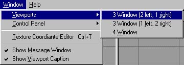
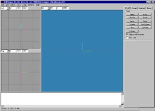
3 Window (2 Left, 1 Right)
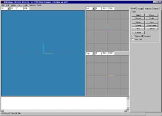
3 Window (1 Left, 2 Right)
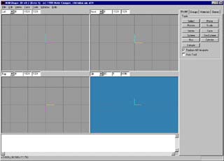
4 Window
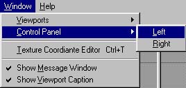
It is also possible to have the editing tabs column on the left or right. When
the program starts up, they are on the right as a default. If you select Window/Control
Panel/Left, then it will switch sides. Naturally selecting Window/Control
Panel/Right will switch it back again:
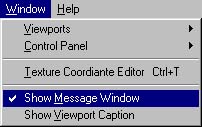
The text window at the bottom of the screen is also optional.
Select Window/Show Message Window to deactivate it and again to re-activate it.
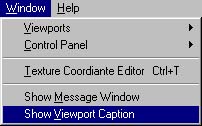
Finally, it is possible to activate Window captions that have coordinate
dialogues and a drop-down menu for each viewport allowing you to quite quickly
change the viewpoint of the port.
Select Window/Show Viewport Caption
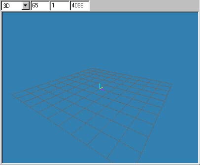
Your viewports will now look like this: With the boxes at the top.
Once you have set up your desired layout, you can then customise individual
viewports.
It is possible to switch between viepoints in the viewports.
If you have the Viewport caption activated then simply click the drop-arrow on
the menu in the top-left corner of the viewport:
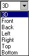
By selecting any of the viewpoints in the list, your viewport will change to
that viewpoint. Clicking 'Front' will present you with an elevation of your
model from the front. 3D shows your model in 3D view.
If you don't have the Viewport dialogue activated, then you can simply
right-click in the viewport and from the menu that appears, select 'Projection',
and you will then get the same list to choose from:
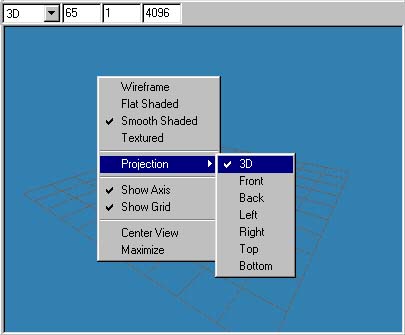
Aside from Projection, there are other options on the menu to choose from:
The first batch are rendering options:
WIREFRAME - this sets the viewport to render all objects in it as a wireframe
mesh.
FLAT SHADED - This will render the object as solid and with it's facets clearly
visible.
SMOOTH SHADED - Similar to FLAT SHADED but the edges of the facets are blended
in so that the whole model appears to have one continuous smooth surface.
TEXTURED - If your model has a texture applied then the model will be drawn as a
solid object with the skin texture drawn on it. Before it has been skinmapped,
your model will simply change colour. If no texture is applied then it will
appear similar to SMOOTH SHADED.
NOTE: The above options are only available in 3D view. Non-3D views can only be
viewed as wireframe.
The next two options are gizmo commands.
SHOW AXIS - switches the xyz gizmo in the centre of the screen on and off.
SHOW GRID - switches the grid on and off.
The final two options are viewport settings.
CENTER VIEW - will centre the viewport if you have dragged it off-centre.
MAXIMISE - draws the selected viewport at full screen size.
VIEWPORT CONTROLS
The view can be zoomed by holding down the shift key and the left mouse button
and dragging the mouse vertically. This will not work if the 'Select' button
under the 'Model' tab is activated.
The view can be 'panned' or 'dragged' by holding down the CTRL key and the left
mouse button and moving the mouse.
In 3D views, holding down the shift key and the left mouse button will rotate
the view in a 360 degree arc in all directions. This cannot be done in non-3D
views.
LOADING MODELS
There is at present only five ways of importing model meshes into Milkshape:
MS3D - Milkshape's native format
Half-Life SMD - The files that are exported from MAX and used to create MDLs
MDL - the final form of file that Half-Life uses in the game.
MD2 - Quake2's model format.
Wavefront OBJ - Actually not sure about this one. Lightwave?
I understand that 3DS (not MAX) and ASC (ascii) importing may be implemented in
later versions.
To load in a model, simply go to File and select either 'Open' or 'Import'.
'Open' only allows you to access 'MS3D' files.
'Import' allows you to open files of the other kind listed.
The model should appear on the screen in your viewport.
The 'Merge' option under Files allows you to import another MS3D file into your
current project. This is handy for importing skeletons or seperate model parts.
CREATING A PRIMATIVE OBJECT
Usually the first port of call for making models from scratch. It is possible to
generate primative objects as a starting point in Milkshape. Using the tools
under the 'Model' tab:
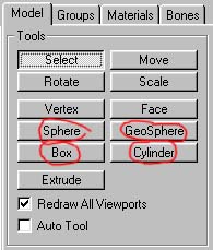
Sphere
A basic sphere made up of grided squares (two triangular faces).
The ammount of vertical segments ('stacks') and horizontal divisions ('slices')
can be adjusted by altering the 'Stacks' and 'Segments' values before drawing
the sphere:
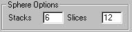
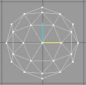
For example, The default value is set to 6 'stacks' and 12 'slices'. Here we see
an example of such a sphere:
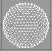
Now if I set the stacks to 12 aswell, we can see that there are still the same
ammount of segments around the sphere but from bottom to top, there are now
twelve segments instead of 6.
To draw the Sphere, place the pointer on the screen where you want the Sphere's
centre point to be, then click and hold down the left mouse button. Drag the
mouse pointer to where you want the Circle's outer edge or 'radius' to be and
release the left mouse button. You will see the sphere grow from the initial
click point to your current pointer position as you drag.
Box
A six-sided cube of variable dimensions
Box has no parameters, simply click and hold down the left mouse button in the
viewport where you want the initial corner of the box to be. Drag the pointer to
where you want the diametrically opposite corner to be and release the left
mouse button. You will see the box grow as you drag the mouse.
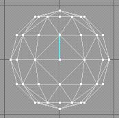
Geo-Sphere
Another form of sphere, but this time made up of triangular
faces that interlock to give the surface of the sphere a much less faceted look,
resulting in a smoother looking sphere.
Here we see only one parameter: 'Depth' This determines the ammount of triangles
in the sphere. Setting the parameter to 1 gives us a fairly simple geosphere:
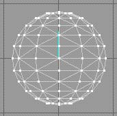
However, setting it to it's maximum level of 3, gives us a highly complex
geosphere:
NOTE:It is possible to input a value up to 9 but only values 1 to 3 will have an
effect. Drawing is done the same as the standard sphere, by clicking and holding
the left mouse button at the desired centrepoint and then dragging to the
desired radius of the sphere. The sphere will grow as you drag.
Cylinder
The cylinder is a peculiar beast. Like the sphere, it also
has 'stacks' and 'slices' and the values work the same way.
However, drawing the sphere can be done two different ways. Either way the
cylinder will always draw with it's ends facing up and down.
In a vertical view (front, back, left, right), you position the pointer where
you want the one corner of the cylinder to be (I say corner because obviously it
looks like a rectangle on the screen), and then holding down the left mouse
button drag the pointer. The Cylinder will grow as you drag. The diameter of the
cylinder is scaled uniformly as you drag left or right and the height is set by
the distance you drag vertically.
In top or bottom view, the cylinder is drawn as a circle that scales uniformly
as you drag the mouse pointer left or right and the height is set automatically.
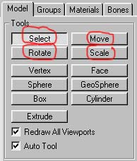
MESH EDITING TOOLS
There are several tools for moving,scaling and rotating your selected vertexes
or faces. They are also under the 'Model' tab:
The key thing to remember about these tools is that they will ONLY work on
selected vertexes or faces. IF you wish to affect your whole model then the
whole model must be selected.
ALSO these tools will only work in non-3D viewports.
SELECT
This is the tool you use to literally select the vertexes,
faces or groups. You use it by drawing a selection box around the vertexes or
faces that you want to affect.
To draw a selection box, click on the screen to set your initial corner and,
holding down the left mouse button, drag the mouse and a box will appear and
grow as you drag. Any vertexes or faces inside the box when you release the
mouse button will be selected and light up red.
NOTE: faces will only be selected if at least one of their corners is inside the
box.
An alternative way to select faces is individually: If you set the select option
to 'Face' and uncheck 'By Vertex' then you can select individual triangles by
clicking in them.
Now it's possible that you selected a few vertexes or faces that you did not
want. If that is the case, hold down the SHIFT key and the RIGHT mouse button
and drag a smaller box around only the unwanted faces. They will deselect,
leaving the others still selected.
It is possible you didn't get all of the vertexes/faces that you wanted. If tis
is the case, hold down the SHIFT key and the LEFT mouse button and drag a box
around the extra vertexes/faces that you want.
It might take a few goes to get it exactly right.
How do you set it to select faces or vertexes? Well when the Select button is
active, you will notice a parameters box lower down:
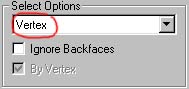
Where it says 'Vertex' ringed in red, if you drop the menu down by using the
arrow on the end, you will see three options: Vertex, Face and Group.
Set to vertex, only vertexes will be selected on your mesh.
Set to Face, only Faces will be selected on your mesh.
When set to group, then a whole mesh sub-group will be selected if at least one
of it's faces is included in the selection box. You needn't concern yourself
with this right now. Groups come into it much later on during the skinmeshing
tutorial.
Okay, so it's time to do unspeakable things to our selected vertexes.
The three tools that will allow you to do this are the Move, Scale and Rotate
tools.
MOVE
Quite simply, you click in the desired viewport and drag the mouse. The selected
Faces/Vertexes will move in that direction corresponding with the mouse pointer.
It is possible to restrict the movement and also manually type in movement
parameters for exact repositioning.
At the bottom of the Tools rollout panel when the Move button is active, you
will see three X,Y and Z buttons accompanied by corresponding type-in fields.
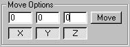
In the image shown, all three X,Y and Z buttons are activated. If you deactivate
any of them, movement in those directions will be restricted. For example if I
deactivate the Y button then I will not be able to move my selected vertexes/faces
vertically in the front or side views.
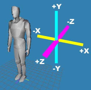
It's worth mentioning at this point that the three directions are as follows:
X is left to right, horizontally
Y is vertical
Z is back and forth horizontally. This is constant in every view, for example,
in 'Front' view X would be horizontal movement whereas in 'Left' or 'Right' view
Z is horizontal movement.
This might take some getting used to so experiment a bit.
Above each button is a field that will allow you to manually type in the ammount
by which you wish the model to move. Positive numbers will move the model in one
direction and negative numbers will move the model the opposite direction.
In X positive numbers move the model to the right ('front' view) and negative
numbers will move the model to the left ('front' view).
In Y positive numbers move the model upwards ('front' or 'side' view) and
negative numbers move the model down (front and side views)
In Z positive numbers move the model forwards (down in 'top' view) and negative
numbers move it backwards (up in 'top' view).
Confused yet? Well, I've made this little illustration to help a bit...
NOTE: any manual type-in adjustments will not take effect until the button
alongside the fields is clicked.
SCALE
It is possible to resize your mesh not just universally but in different
directions.
Using the 'Scale' tool as it is, you can scale selected vertexes/faces in two
directions:
Holding down the left mouse button and dragging left and right will scale the
selected vertexes/faces horizontally. Dragging up and down will scale them
vertically. The effects will vary depending on which view you are using.
As with movement it is also possible to restrict the direction that you scale in
by deactivating the X,Y and Z buttons at the bottom of the tools rollout.
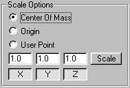
The same rules apply to the buttons and the manual type-in fields that do to the
MOVE tool (see above). However, in the manual type-in fields the values are
different. Here we see that the default values are 1.0 instead of in move where
they are 0.0.
1.0 represents the actual scale of the selected vertexes/faces. If you were to
set the values to 0.5 then they would scale in the relevant direction to half
their current size. On the other hand If the fields were set to 2.0 then they
would become twice their current size.
NOTE As with Movement, the manual type-in fields will not have any effect until
you have clicked the button alongside.
What we also have here which is new is the ability to set the centrepoint from
which the selected objects are scaled.
You will notice above the X,Y and Z buttons, three radio boxes entitled: 'Center
Of Mass', 'Origin' and 'User Point'.
Depending on which is checked, will depend on the effects of your scale.
'Center of Mass' means that the scale will radiate out from a common centre to
your selected vertexes and faces.
'Origin' is the pink,yellow and blue gizmo at the centre of the screen. where
the three coloured lines converge is the absolute centre of your workspace. This
is known as the, 'Origin'. If the 'Origin' box is checked, then the scale will
radiate from the Origin point.
'User Point' means that the scale will radiate from the point at which the mouse
pointer was when you clicked the mouse button down. This point is set regardless
of where you drag the mouse to.
ROTATE
It is possible to rotate selected vertexes/faces. Hold down
the left mouse button and drag vertically. The actual direction of rotation
depends on the view that you are currently using.
As with all of the above tools, it is possible to restrict the direction of a
rotation and it is also possible to manually type-in rotational data for
absolute accuracy. This time, however, the data in the fields is in degrees of
rotation so the values go up to 360 before the selected vertexes/faces perform a
full rotation.
Once again the Rotate tool has three centre point options: 'Center of Mass', 'Origin'
and 'User Point'. They dictate the point around which the selected vertexes/faces
will rotate and they have the same properties as those listed under the Scale
tool.
TIP: If you have 'Auto Tool' checked then the tools buttons will automatically
switch between Select and the tool you are using every time you click the left
mouse button.
Well, that's it. I haven't mentioned the 'Vertex', 'Face' and 'Extrude' buttons
because they will be used extensively in the modelling tutorial.
Tutorial created by Scarecrow,
THANK YOU !!!
©
http://www.Planetfortress.com/TF2Models
TF2 is trademark of Valve
Software and of Sierra Online.
© 2000 TF2 MODELS - Hosted by Planetfortress
Web designer/Webmaster : IXNAY